Having trouble getting model to display with tangents.
Material.xml:
<material>
	<technique name="Techniques/DiffNormal.xml" quality="0" />
	<texture unit="diffuse" name="Textures/StoneWall4/white.jpg" />
	<texture unit="normal" name="Textures/StoneWall4/Wall Stone 004_NRM.jpg" />
</material>
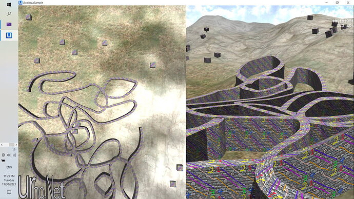
Note the diffuse map is white, to clearly see effect of normal map.
First, WITHOUT tangents on element - Position | Normal | TexCoord1 here is that material, used on standard Box model, and on one of my walls:
It is correct on Box. On wall, it is having effect, but of course normals are not right - as rotate around the object, at certain positions lighting effect changes dramatically.
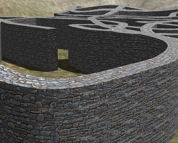
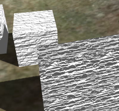
When add tangent to element - Position | Normal | TexCoord1 | Tangent, it is good on top, but not on sides (the box can be seen behind it, still good.). [I assume that what the Box shows, on facing side, is what it should match.]
This is the vertex data for the top quad and side quads:
|
// TOP |
|
(-31, 8.65625, -60), (0.0622449, 0.995919, 0.0653572), (0, 0), (0, -0.0654841, 0.997854, 1) |
|
(-31, 8, -50), (0.0622449, 0.995919, 0.0653572), (2.50744, 0), (-0.00038677, -0.0654601, 0.997855, 1) |
|
(-29, 8, -50), (0.0622449, 0.995919, 0.0653572), (2.50744, 0.50178), (-0.000773855, -0.065436, 0.997856, 1) |
|
(-29, 8.53125, -60), (0.0622449, 0.995919, 0.0653572), (0, 0.50178), (-0.00038677, -0.0654601, 0.997855, 1) |
|
// SIDE 1 |
|
(-29, 8.53125, -60), (1, -0, -0), (0, 0), (0, -0.0530502, 0.998592, 1) |
|
(-29, 8, -50), (1, -0, -0), (2.50744, 0), (0, -0.0530502, 0.998592, 1) |
|
(-29, -0.5, -50), (1, -0, -0), (2.50744, 2.12519), (0, -0.0530501, 0.998592, 1) |
|
(-29, 0.03125, -60), (1, -0, -0), (0, 2.12519), (0, -0.0530502, 0.998592, 1) |
|
// SIDE2 |
|
(-31, 8, -50), (1, -0, -0), (-2.5093, 0), (0, 0.0654841, -0.997854, -1) |
|
(-31, 8.65625, -60), (1, -0, -0), (0, 0), (0, 0.0654842, -0.997854, -1) |
|
(-31, 0.15625, -60), (1, -0, -0), (0, 2.12519), (0, 0.0654842, -0.997854, -1) |
|
(-31, -0.5, -50), (1, -0, -0), (-2.5093, 2.12519), (0, 0.0654842, -0.997854, -1) |
(I don’t show the “end” quad - it is correctly solid gray because its in shadow and texture is solid white. This can be seen on Box as well.)
I’ve verified that position, normal, and UV (texcoord) are all same as in the previous image - only tangent values are new.
Are there any unit tests that show correct Tangent output? I rewrote the code in C#: Avalonia_4/Tangent1.cs at Main · ToolmakerSteve/Avalonia_4 · GitHub
I don’t know how to determine if those tangent values are good.
UPDATE
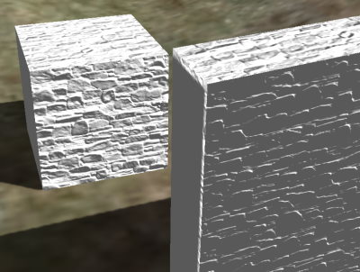
If I swap endpoints so that wall is drawn right-to-left instead of left-to-right, the lighting is correct - looks just the same on wall as on box. The relevant (good) data:
|
// TOP |
|
(-29, 8, -50), (0, 0.998592, 0.0530502), (0, 0), (0, 0.0530502, -0.998592, 1) |
|
(-29, 8.53125, -60), (0, 0.998592, 0.0530502), (2.5093, 0), (0, 0.0530502, -0.998592, 1) |
|
(-31, 8.65625, -60), (0, 0.998592, 0.0530502), (2.5093, 0.500847), (0, 0.0530502, -0.998592, 1) |
|
(-31, 8, -50), (0, 0.998592, 0.0530502), (0, 0.500847), (0, 0.0530502, -0.998592, 1) |
|
// SIDE1 |
|
(-31, 8, -50), (-1, -0, -0), (0, 0), (0, 0.0654841, -0.997854, 1) |
|
(-31, 8.65625, -60), (-1, -0, -0), (2.5093, 0), (0, 0.0654842, -0.997854, 1) |
|
(-31, 0.15625, -60), (-1, -0, -0), (2.5093, 2.12519), (0, 0.0654842, -0.997854, 1) |
|
(-31, -0.5, -50), (-1, -0, -0), (0, 2.12519), (0, 0.0654842, -0.997854, 1) |
|
// SIDE2 |
|
(-29, 8.53125, -60), (-1, -0, -0), (-2.50744, 0), (0, -0.0530502, 0.998592, -1) |
|
(-29, 8, -50), (-1, -0, -0), (0, 0), (0, -0.0530502, 0.998592, -1) |
|
(-29, -0.5, -50), (-1, -0, -0), (0, 2.12519), (0, -0.0530501, 0.998592, -1) |
|
(-29, 0.03125, -60), (-1, -0, -0), (-2.50744, 2.12519), (0, -0.0530502, 0.998592, -1) |
I think I have some issue in my calculation of normals. Both sides have normal pointing same direction, which can’t be right.
I’ll debug that tomorrow.